Wind turbines have become iconic symbols of the global shift toward renewable energy. At the heart of every turbine, the blades perform the critical work of capturing wind and transforming it into usable power. Understanding how a blade for wind turbine systems functions—from aerodynamic design to end-of-life recycling—reveals the remarkable engineering that makes wind power one of the fastest-growing energy sources on the planet.
This guide explores everything you need to know about wind turbine blades: how they generate electricity, what materials give them strength and longevity, how engineers design them for maximum efficiency, and where the technology is heading in the coming decades.
How Wind Turbine Blades Generate Energy
Wind turbine blades are the primary components responsible for converting the kinetic energy of moving air into rotational mechanical energy. Without these carefully shaped structures, turbines would have nothing to harness from the wind.
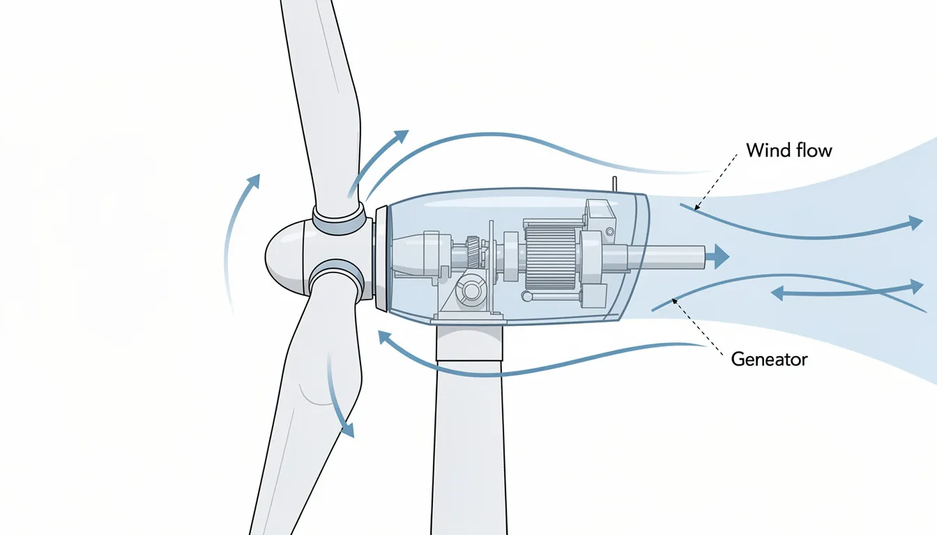
The process works much like an aircraft wing, but in reverse. As wind passes over the blade’s airfoil shape, it creates a pressure difference between the upper and lower surfaces. This generates aerodynamic lift, which causes the rotor to spin. Large onshore turbines typically rotate at speeds between 8 and 20 rpm—slower than most people expect, but generating enormous torque.
The rotation of the rotor drives a main shaft connected to a gearbox (or direct-drive system in some modern designs), which increases rotational speed to levels suitable for the generator. The generator then converts this mechanical energy into electrical power that flows into the grid.
Here’s a practical example: a modern 4 MW onshore turbine with a rotor diameter of approximately 145 meters can produce electricity for several thousand European homes annually. The swept area of those turning blades captures enough wind energy to power entire communities.
The energy a turbine can capture depends on three key factors:
-
Wind speed (energy increases with the cube of wind speed)
-
Air density at the location
-
The swept area of the rotor (determined primarily by blade length)
This relationship explains why engineers continually push to make blades longer—even small increases in length translate to significant gains in annual energy production.
Blade Size and Power Output
Blade length and rotor diameter are the main drivers of how much energy a turbine can capture from the wind. The relationship is straightforward: longer blades mean larger swept areas, which means more energy extracted from passing air.
Modern wind turbine blades span an enormous range of sizes depending on their application:
|
Category |
Blade Length |
Typical Capacity |
Homes Powered |
|---|---|---|---|
|
Small residential |
2–5 m |
1–20 kW |
1–3 |
|
Community-scale |
15–35 m |
100 kW–1 MW |
50–300 |
|
Utility onshore |
45–75 m |
2–7 MW |
1,500–4,000 |
|
Offshore |
80–118 m |
8–15+ MW |
5,000–18,000 |
Some well-known examples illustrate just how large these structures have become:
-
GE Haliade-X: 14–15 MW capacity with blade length of approximately 107 meters
-
Vestas V236-15.0 MW: blade length of 115.5 meters—longer than a football field
-
Typical 3.6 MW onshore turbine: approximately 65-meter blades
The physics behind this scaling is compelling. Swept area grows with the square of the rotor radius, so adding just a few meters to blade length can boost annual energy production by 10% or more. This explains the relentless drive toward bigger rotors, particularly for offshore wind energy installations where space constraints are minimal and higher capacity factors justify the investment.
Key Parts of a Wind Turbine Involving the Blades
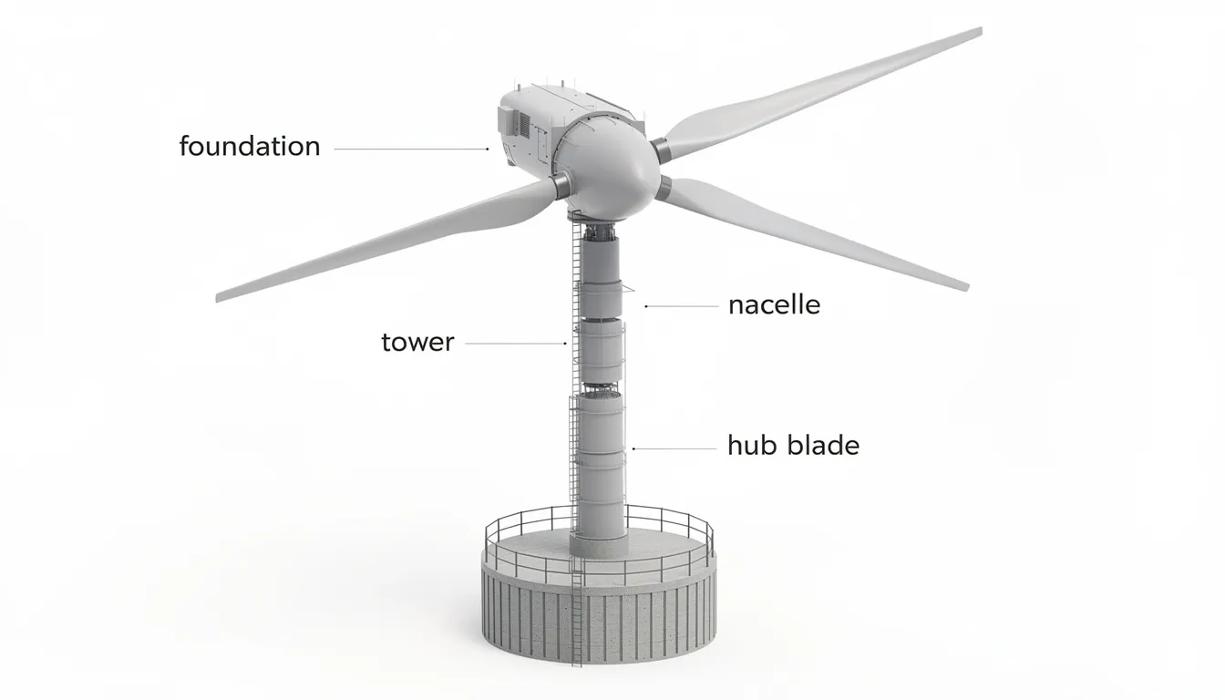
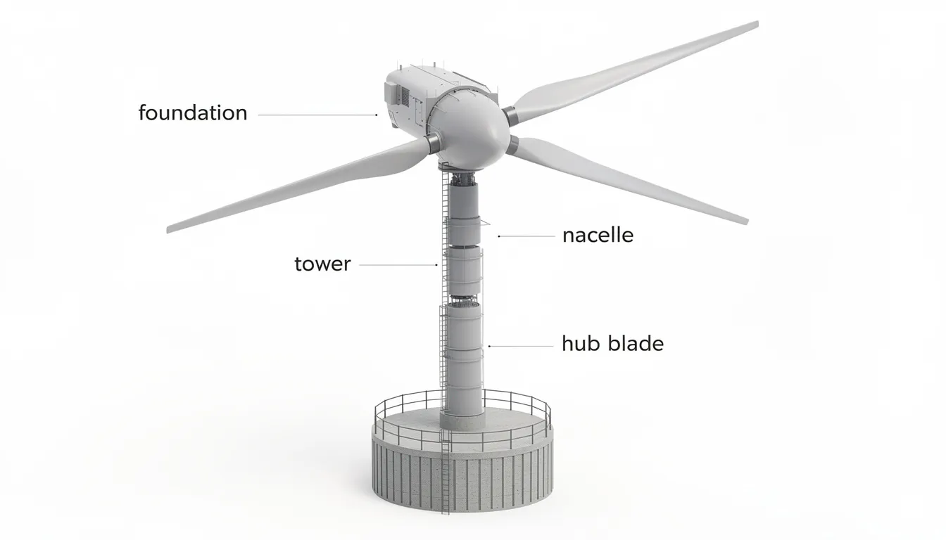
Wind turbine blades don’t operate in isolation—they’re part of an integrated system where each component plays a specific role in energy capture and conversion. Understanding these connections helps explain why blade design involves so many engineering trade-offs.
The blades themselves capture wind, create lift, generate torque, and drive the rotor. But they rely on several other critical components:
-
Hub: The central connection point where all blades attach to the rotor. Houses pitch bearings and actuators that control blade angle.
-
Rotor: The complete assembly of blades plus hub. This is what actually rotates to transfer mechanical energy into the drivetrain.
-
Low-speed shaft: Connects the rotor to the gearbox, rotating at the same speed as the blades (typically 8–20 rpm).
-
Gearbox: Increases rotational speed from the low-speed shaft to drive the generator at 1,000–1,800 rpm. Some modern designs use direct-drive generators instead.
-
Pitch system: Hydraulic or electric actuators that rotate each blade around its longitudinal axis to optimize power capture or protect against storms.
-
Yaw system: Motors and drives that rotate the nacelle so blades always face into the wind.
-
Nacelle: The housing atop the wind turbine tower containing the gearbox, generator, and control systems.
-
Tower: The steel or concrete structure supporting the nacelle and rotor at heights typically ranging from 80 to 140 meters.
The controller acts as the brain of the operation, using data from anemometers and wind vanes to adjust pitch and yaw angles continuously. This coordination ensures the turbines extract maximum power while staying within safe operating limits.
Materials Used for Wind Turbine Blades
Wind turbine blades are large composite structures that combine reinforcing fibers with polymer matrices to achieve the necessary strength, stiffness, and low weight. Getting this balance right is essential—blades must withstand decades of cyclic loading while remaining light enough to rotate efficiently.
Since approximately 2000, most modern blades have been constructed primarily from glass fiber-reinforced plastic (GFRP) using epoxy or polyester resin. For longer offshore blades, manufacturers incorporate carbon fiber in critical load-bearing areas like the spar caps to boost stiffness without excessive weight gain.
Typical dimensions and weights illustrate the scale involved:
-
50-meter onshore blade: 7–10 tonnes
-
80–100-meter offshore blade: 25–35 tonnes
-
115-meter next-generation blade: 40+ tonnes
The internal structure uses sandwich construction with balsa wood or PVC/PET foam cores in shear webs and shell panels. This approach increases stiffness dramatically without adding proportional weight—critical when gravity loads already dominate the stress picture on longer blades.
Recent material innovations are changing the landscape:
-
Thermoplastic resins: Introduced in pilot blades around the early 2020s, these materials can be chemically recycled at end of life
-
Bio-based resins: Under development to reduce embodied carbon by 50–70% compared to traditional epoxies
-
Nano-reinforcements: Carbon nanotubes and graphene nanoplatelets showing promise for extending fatigue life by factors of 10–15x in laboratory testing
The outer surface receives protective gelcoats 1–2 mm thick to resist UV degradation and leading-edge erosion from rain and dust impacts. Without this protection, blades would lose significant performance within just a few years.
Blade Design: Aerodynamics and Geometry
Blade shape is optimized like an aircraft wing to maximize lift, minimize drag, and control structural loads throughout the operating envelope. Engineers use computational fluid dynamics (CFD) to simulate airflow and refine designs before building expensive prototypes.
Three geometric parameters define blade shape:
-
Chord: The width of the blade at any given point along its length
-
Twist: The angle of the airfoil relative to the plane of rotation
-
Taper: How the chord changes from root to tip
Near the root, blades are wider and more twisted to handle high structural loads and generate starting torque. Toward the tip, they become slimmer and less twisted for aerodynamic efficiency where tangential velocities are highest.
Most utility-scale installations use three blades in an upwind configuration—meaning the rotor faces into the wind ahead of the tower. This design offers the best balance of energy capture, structural loads, visual appearance, and noise characteristics. The airfoil profiles derive from aviation heritage (NACA families and their descendants) but have been refined specifically for wind applications.
Tip-speed ratio (λ) describes the relationship between blade tip speed and incoming wind speed. Large turbines typically operate at ratios between 6 and 9. Higher values increase energy capture but also raise noise levels and structural loads—another engineering trade-off.
Offshore blades often feature swept or curved tips to:
-
Reduce aerodynamic noise
-
Improve load control during gusts
-
Maintain safe tower-blade clearance during extreme deflections
These design refinements can reduce induced drag by 5–10%, translating directly to higher annual energy production.
Blade Size Categories and Typical Applications
Blade length categories correspond closely to installation context and power requirements. The right size depends on wind resources, grid connection, and project economics.
Small blades (2–5 meters) serve turbines in the 1–20 kW range. You’ll find these on:
-
Residential properties in windy regions
-
Telecommunication masts in remote areas
-
Boats and off-grid cabins
-
Agricultural water pumping systems
Mid-size blades (10–35 meters) power turbines from 100 kW to 1 MW. Typical applications include:
-
Farm installations supplementing grid power
-
Industrial sites with consistent wind exposure
-
Small community wind projects
-
Developing regions with distributed generation needs
Large onshore blades (45–75 meters) dominate the utility-scale market, powering 2–7 MW turbines. These have been deployed widely across Europe, North America, and Asia since about 2015. A single rotation of these blades sweeps an area larger than many people’s homes.
Offshore blades (80–118 meters) represent the cutting edge, powering 8–15+ MW turbines in demanding marine environments. Major deployment locations include:
-
North Sea (UK, Germany, Denmark, Netherlands)
-
Baltic Sea
-
US East Coast
-
Coastal China
To put the size in perspective: at 115 meters, the longest current blades exceed the wingspan of an Airbus A380 (80 meters) and approach the length of a football field. Standing one on end would tower above most 30-story buildings.
Control Systems: Pitch, Yaw and Safety of Blades
Active control systems protect blades from extreme loads while optimizing power capture across varying wind conditions. Without these systems, blades would quickly fail from fatigue or storm damage.
The pitch system represents the primary control mechanism. Hydraulic or electric actuators inside the hub rotate each blade around its longitudinal axis, changing the angle of attack relative to incoming wind. This enables:
-
Fine adjustments for maximum power extraction in normal winds
-
Feathering blades to near-zero lift during storms (reducing loads by 90%+)
-
Stopping the rotor for maintenance access
-
Controlled startup and shutdown sequences
Operational pitch angles typically range from 0° (maximum power) to 90° (fully feathered). The transition can happen in seconds when storm gusts threaten.
The yaw system uses motors and gear drives to rotate the entire nacelle so blades face into the wind. Modern utility-scale turbines are almost exclusively upwind designs, requiring active yaw control. The system tracks wind direction continuously and makes gradual corrections to maintain optimal alignment.
The controller coordinates everything using data from:
-
Cup anemometers measuring wind speed
-
Wind vanes detecting direction
-
Accelerometers monitoring vibration
-
Temperature sensors throughout the drivetrain
Typical operating parameters include:
-
Cut-in wind speed: 3–5 m/s (when generation begins)
-
Rated wind speed: 11–15 m/s (full power output)
-
Cut-out wind speed: 25 m/s (approximately 55–65 mph, when turbine shuts down for protection)
These control systems make modern wind turbine operation remarkably safe and reliable, with availability factors routinely exceeding 95%.
How Long Wind Turbine Blades Last
Blade lifespan is typically designed for 20–25 years, matching the overall turbine lifetime. This means surviving 10^8 to 10^9 fatigue cycles—an engineering challenge comparable to aerospace structures.
Many commercial turbines installed in Denmark, Germany, Spain, and the US during the 1990s and early 2000s are now being repowered. Original blades from these projects are being removed after two decades of service, providing real-world validation of design life predictions.
Key degradation mechanisms include:
-
Fatigue from cyclic loading: Each rotation subjects blades to fluctuating stresses as they pass through varying wind conditions and tower shadow effects
-
UV exposure: Degrades polymer matrices and protective coatings over time
-
Leading-edge erosion: Rain and dust impacts remove material at rates of 0.1–1 mm per year, reducing aerodynamic efficiency
-
Lightning strikes: Large turbines experience 100–200 lightning events over their lifetime, with 5–10% causing visible blade damage annually
-
Manufacturing defects: Porosity, delaminations, and bonding issues that may propagate under operational loads
Regular inspections extend practical blade life toward 25–30 years. Typical maintenance practices include:
-
Visual inspections 1–2 times annually
-
Drone-based photography and thermography
-
Rope-access technicians for detailed assessment and repairs
-
Leading-edge protection tape or coating application
-
Embedded sensors for continuous structural health monitoring
Detecting damage early allows cost-effective repairs rather than complete blade replacement. A well-maintained blade can often outlast its original design life by 20–40%.
Manufacturing and Installation of Blades
Manufacturing wind turbine blades involves specialized processes that combine aerospace precision with industrial scale. The journey from raw materials to operational blade typically takes 4–6 weeks.
Design and mold preparation come first. Steel or composite molds up to 120 meters long are precision-machined to produce the exact aerodynamic shape. These molds represent significant capital investments—often $2–5 million each.
Layup and infusion follow. Technicians place dry fiberglass or carbon fiber fabrics into the mold, building up dozens of layers in precise orientations. Foam or balsa cores go into sandwich sections. The mold is then sealed under vacuum, and low-viscosity epoxy resin (typically 200–500 centipoise) is pulled through the fabric stack. This vacuum-assisted resin transfer molding (VARTM) achieves fiber volume fractions of 55–60% with void content below 1%.
Curing and bonding complete the structure. Blades typically consist of two shell halves plus internal shear webs, bonded together with structural adhesives. Heat curing at 60–80°C ensures full resin crosslinking. Total cycle times run 24–48 hours for large blades.
Transport presents unique challenges for blades over 70 meters. Road transport requires:
-
Specialized extendable trailers
-
Route surveys for tight turns and bridge heights
-
Nighttime movements with escort vehicles
-
Sometimes blade rotation for obstacle clearance
Offshore blades often travel by ship directly from factory ports to installation sites, avoiding road constraints entirely.
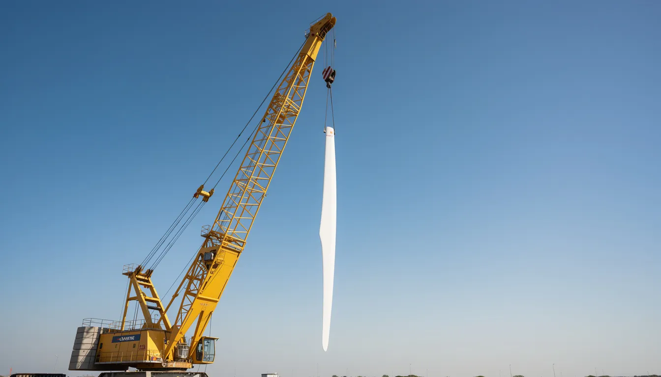
Installation requires heavy lifting. Onshore projects use crawler cranes with 600–1,200 tonne capacity, lifting individual blades to hub heights of 80–140 meters. Offshore installations rely on jack-up vessels or heavy-lift ships, often in challenging sea conditions. Each blade lift typically takes 2–4 hours, with weather windows carefully planned.
Recycling and Reuse of Wind Turbine Blades
Wind turbines are approximately 96% recyclable by mass—steel towers, copper generators, and concrete foundations all have established recycling pathways. But composite blades present a tougher challenge, and the industry is actively working to close this gap.
Many first-generation blades from 1990s and early 2000s projects have been landfilled or incinerated, creating public concern and regulatory pressure. Europe alone landfills approximately 50,000 tonnes of blade material annually, a situation that’s increasingly unacceptable as wind energy scales up.
Current solutions for end-of-life blades include:
-
Mechanical shredding: Grinding fiberglass into particles used as filler in construction materials or processed in cement kilns where the glass becomes aggregate and organic components provide fuel value
-
Pyrolysis: Heating blade material in oxygen-free environments to recover fibers and generate fuel gases
-
Cement co-processing: Complete blades fed into cement kilns, replacing traditional raw materials and fuels
Creative reuse projects are turning retired blades into second-life structures:
-
Bicycle shelters and bus stops
-
Pedestrian bridges
-
Playground equipment
-
Noise barriers along highways
-
Architectural features and public art
Looking forward, thermoplastic blades and recyclable resin systems aim for near-100% recyclability. These materials can be chemically depolymerized at end of life, recovering 95%+ of original fiber content for reuse. Pilot projects using thermoplastics like Arkema’s Elium resin demonstrate the concept, with commercial deployment expected to accelerate through the late 2020s.
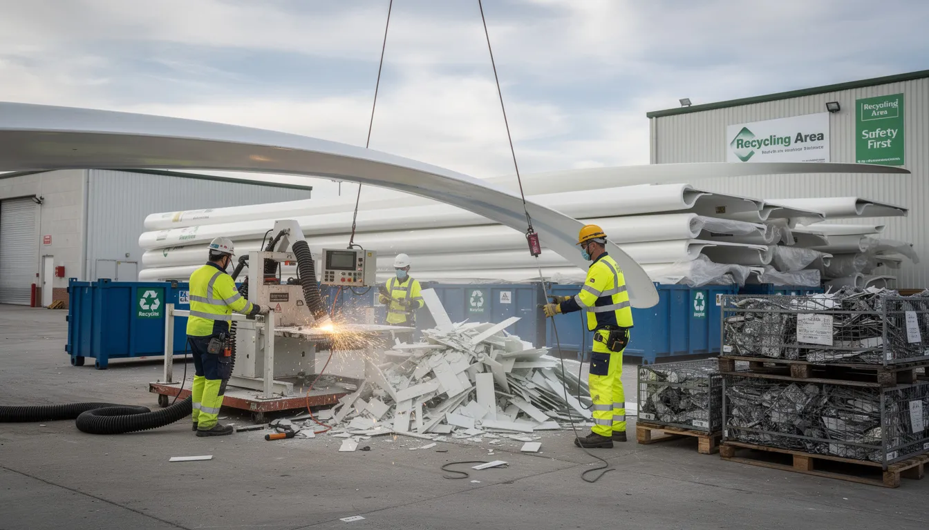
The industry target is clear: by 2040, no blade material should reach landfill. Achieving this will require continued innovation in both materials and recycling infrastructure.
Future Trends in Wind Turbine Blade Technology
Blades remain one of the most rapidly evolving technology areas within wind power, with innovations directly impacting project economics and deployment potential.
Continued upscaling shows no signs of slowing. Designs beyond 120-meter blade length for 18–20 MW offshore turbines are expected around the late 2020s. These machines will generate electricity equivalent to tens of thousands of homes each, making offshore wind energy increasingly cost-competitive with fossil fuels.
Digitalization is transforming blade operations. Structural health monitoring using embedded fiber optic sensors and strain gauges enables:
-
Real-time load tracking
-
Early damage detection
-
Predictive maintenance scheduling
-
Extended operational life beyond original design targets
Material evolution continues across multiple fronts:
-
Increased carbon fiber in spar caps for longer, lighter blades
-
Bio-based resins reducing embodied carbon by 50–70%
-
Fully recyclable thermoplastic composites entering commercial production
-
Nano-reinforcements boosting fatigue life by 15–50x in laboratory testing
Design innovations address practical challenges:
-
Segmented blades (2–4 sections) for rail transport of 100+ meter structures
-
Adaptive trailing edges that morph during operation for load control
-
Advanced tip shapes reducing noise and improving efficiency by 5–10%
-
Active aeroelastic tailoring that lets blades bend favorably under load
These advances connect directly to global climate targets. Achieving net-zero emissions by 2050 requires massive expansion of wind power capacity—from approximately 900 GW today to 6,000+ GW. Blade innovation enables the larger, more efficient, and more durable turbines needed to meet this challenge at competitive costs projected to reach $20–30/MWh for offshore wind by 2035.
The future of wind energy depends on continued progress in blade technology. Scientists and engineers worldwide are working to make each generation of blades longer, lighter, more efficient, and fully recyclable. For anyone interested in renewable energy’s role in addressing climate change, watching blade innovation unfold offers a window into how technology can harness natural forces at remarkable scale.